 EN
EN


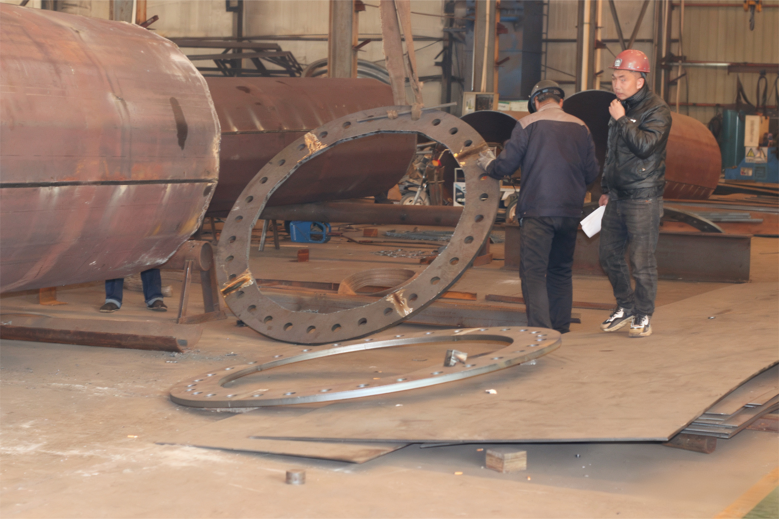
Gdy inżynierowie i menedżerowie projektowi omawiają integralność konstrukcyjną infrastruktury linii przesyłowych wysokiego napięcia, niewiele tematów wymaga tak dużej precyzji jak połączenie wieży elektrycznej z jej fundamentem. Ten punkt połączenia nie jest jedynie połączeniem mechanicznym — stanowi on najważniejszy przejście konstrukcyjne w całym systemie, odpowiadające za przenoszenie ogromnych obciążeń ze stalowej nadbudowy do gruntu. Wieża elektryczna musi wytrzymać dziesięciolecia działania ciśnienia wiatru, aktywności sejsmicznej, obciążenia lodem oraz naprężenia przewodów, a każda z tych sił skupia się ostatecznie w szczegółach połączenia przy podstawie. Poprawne zaprojektowanie tego połączenia nie jest kwestią opcjonalną — stanowi ono podstawowy warunek wstępnym zapewniający bezpieczną i długotrwałą pracę sieci elektroenergetycznej.
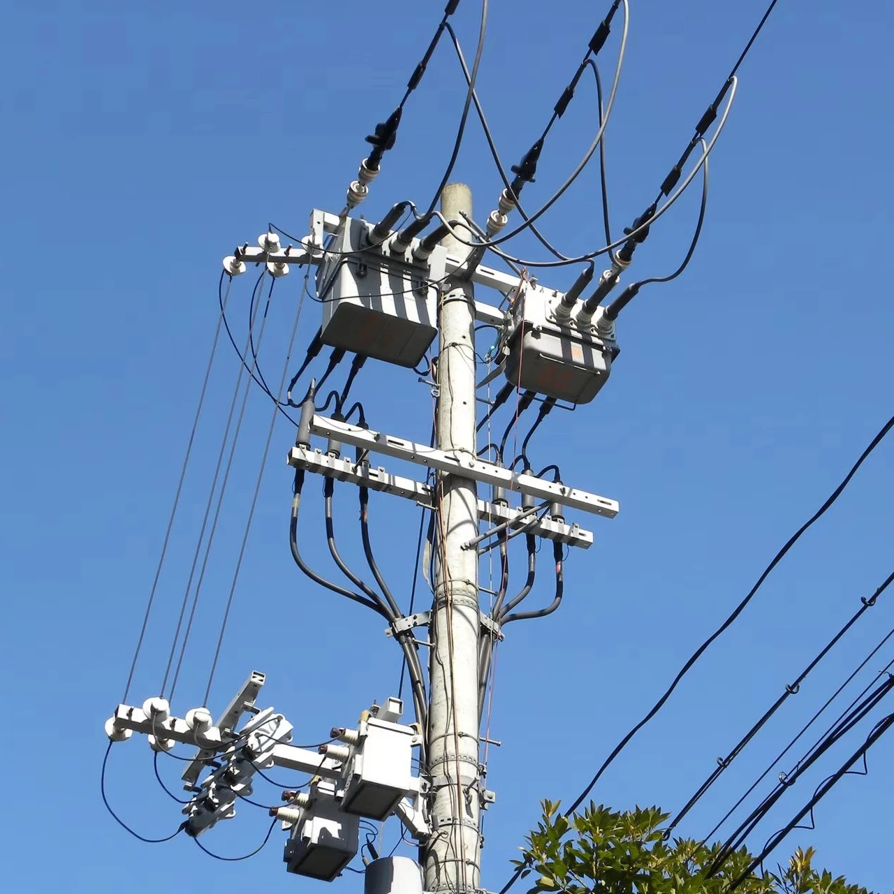
Znaczenie tego szczegółu jest często niedoszacowane podczas wstępnego budżetowania i planowania projektu. Zespoły zakupowe skupiają się na wysokości wieży, przepustowości przewodnika oraz jakości ocynkowania, podczas gdy połączenie z fundamentem traktowane jest jako standardowy etap budowlany. W rzeczywistości źle zaprojektowane lub nieprawidłowo wykonane połączenie między wieża elektryczna a jej fundamentem może spowodować postępujące uszkodzenie konstrukcyjne, zagrozić niezawodności linii oraz stworzyć poważne zagrożenia dla bezpieczeństwa personelu serwisowego i społeczności zamieszkujących okoliczne tereny. Zrozumienie, dlaczego to połączenie jest tak istotne — oraz czym ono zarządza — stanowi niezbędną wiedzę dla każdej osoby uczestniczącej w podejmowaniu decyzji dotyczących infrastruktury przesyłowej.
Rola mechaniczna połączenia wieży z fundamentem
Jak obciążenia przenoszone są przez układ
Wieża elektryczna jest narażona na działanie wielu sił jednoczesnych, które nie działają w sposób jednorodny. Obciążenia pionowe pochodzą od własnej masy konstrukcji wieży oraz masy przewodów i elementów zaciskowych. Obciążenia poziome pochodzą głównie od wiatru działającego na korpus wieży oraz na przewody rozpięte między przęsłami. Siły skręcające i unoszące powstają w przypadku asymetrycznego układu przewodów lub awarii przewodów (przerwania przewodu). Wszystkie te siły muszą zostać odpowiednio rozłożone i przekazane przez szczegół połączenia do fundamentu znajdującego się poniżej.
Szczegóły połączenia decydują o tym, jak gładko przebiega ten przekaz obciążenia. Dobrze zaprojektowane połączenie podstawy wykorzystuje precyzyjnie obliczone rozmieszczenie śrub kotwiących, odpowiednio dobrane wymiary płyty podstawowej oraz odpowiednie warstwy zaprawy w celu jednolitego rozprowadzenia naprężeń kontaktowych. Jeśli którykolwiek z elementów tego zespołu jest niedoszacowany, nieprawidłowo wyjustowany lub źle zamontowany, przekazywanie obciążenia powoduje koncentrację naprężeń, które przyspieszają uszkodzenia zmęczeniowe. Wieża elektryczna może wydawać się zewnętrznie strukturalnie bezpieczna, podczas gdy ukryte uszkodzenia postępują już w jej podstawie.
Inżynierowie klasyfikują te awarie połączeń jako awarie wtórne właśnie dlatego, że często zaczynają się one niewidocznie. Korpus wieży pozostaje prosty, przewodniki pozostają pod napięciem, a rutynowe inspekcje wizualne nie ujawniają niczego niepokojącego. Dopiero gdy degradacja osiągnie krytyczny próg, możliwa staje się nagła katastrofalna awaria, często wywołana w przeciwnym razie kontrolowanym zdarzeniem wiatrowym lub zmianą obciążenia. Dlatego też normy projektowe dotyczące fundamentów wież elektrycznych stale wymagają zachowania ostrożnych współczynników bezpieczeństwa w strefie połączenia z podstawą, zamiast polegać na założeniach dotyczących średnich przypadków.
Odporność na wypychanie i przewrócenie
Jednym z najbardziej wymagających mechanicznych wymagań dotyczących połączenia wieży z fundamentem jest odporność na siły unoszące i momenty przewracające. Noga elektrycznej wieży pod wpływem określonych obciążeń doświadcza wypadkowych sił skierowanych ku górze, co oznacza, że śruby kotwiące muszą przenosić siły rozciągające, a nie ściskające. Zjawisko to występuje szczególnie często w konstrukcjach wież kratownicowych, w których poszczególne nogi mają oddzielne fundamenty, a każdy z nich musi niezależnie przenosić zarówno obciążenia ściskające, jak i rozciągające.
Projekt głębokości zakotwienia śrub kotwiących, średnicy śruby oraz wytrzymałości betonu bezpośrednio określa dostępną wartość odporności na siły unoszące. Niewystarczająca głębokość zakotwienia prowadzi do wyciągania się śrub kotwiących, co stanowi jeden z najbardziej drastycznych i nieodwracalnych trybów awarii. wieża przesyłowa systemy. Gdy śruba kotwiąca zaczyna wypychać się przez beton fundamentu, wieża traci stabilność boczną bardzo szybko. To właśnie dlatego każdy zespół inżynierski określający parametry elektrycznej wieży musi traktować szczegół konstrukcji kotwienia z taką samą rygorystycznością, jaką stosuje się wobec samej konstrukcji wieży.
Odporność na moment przewracający wymaga, aby fundament zapewniał stabilną reakcję obrotową. Dla wysokiej wieży elektrycznej przenoszącej wiele przewodów wysokiego napięcia momenty przewracające mogą być znaczne, szczególnie w obszarach o dużych prędkościach wiatru lub przy dużych rozstawach przewodów. Płyta podstawowa i grupa śrub kotwiących muszą łącznie zapewniać wystarczającą nośność na moment, a ta nośność zależy od dokładnych danych geotechnicznych wykorzystywanych w projektowaniu fundamentu. Pominięcie lub przybliżenie badań gruntowych to pozorna oszczędność, która często prowadzi do kosztownych działań naprawczych lub wymiany wieży.
Zgodność materiałów i korozja w strefie połączenia
Dlaczego strefa połączenia stanowi ognisko korozji
Styk między stalową konstrukcją wieży elektrycznej a fundamentem betonowym stanowi szczególnie agresywne środowisko sprzyjające powstawaniu korozji. Beton naturalnie zatrzymuje wilgoć, a strefa bezpośrednio powyżej i poniżej poziomu gruntu podlega cyklicznemu zmaczaniu i wysychaniu oraz potencjalnemu przenikaniu chlorków lub siarczanów w zależności od składu chemicznego gleby. Stal ocynkowana metodą gorącej cieczy, która jest standardowym materiałem ochronnym dla wież przesyłowych, wykazuje doskonałą odporność w pełni narażonych warunkach atmosferycznych, lecz może ulec przyspieszonej korozji przy częściowym zakotwieniu w betonie lub glebie.
Strefa przejściowa — zwykle pierwsze 150–300 mm powyżej i poniżej powierzchni betonu — to miejsce, w którym ocynkowanie jest najbardziej narażone. Jeśli szczegół połączenia nie uwzględnia tego za pomocą odpowiednich systemów powłok ochronnych, uszczelek lub rękawów ochronnych, korozja galwaniczna lub szczelinowa może stopniowo zmniejszać przekrój stalowy. Dla wysokonapięciowej wieży elektrycznej zaprojektowanej do eksploatacji przez 30–50 lat nawet umiarkowane roczne tempo korozji w strefie podstawy może się kumulować, prowadząc do znacznej utraty przekroju i bezpośredniego obniżenia nośności konstrukcyjnej połączenia.
Specyfikacje projektowe, które wyraźnie uwzględniają zagrożenie korozją w strefie połączenia — poprzez dobór materiałów, określenie wymagań dotyczących powłok ochronnych oraz projektowanie odpływu wody — wykazują systematycznie niższe koszty konserwacji w całym cyklu życia obiektu oraz rzadsze przypadki wcześniejszej wymiany elementów. Inwestycja początkowa w szczegóły zapewniające odporność na korozję w miejscu połączenia podstawy wieży elektrycznej należy do decyzji o najwyższym zwrocie z inwestycji podejmowanych w fazie projektowania.
Specyfikacja śrub kotwiących i ich długotrwała integralność
Śruby kotwiące stanowią główny połączenie mechaniczne między stalową wieżą a fundamentem betonowym, dlatego specyfikacja ich materiału ma ogromne znaczenie. Śruby wykonane ze stali wysokowytrzymałej muszą być zgodne z procesem ocynkowania stosowanym w pozostałej części zestawu wieży elektrycznej, aby uniknąć kruchości wodorowej podczas zanurzania w kąpieli cynkowej. Nieodpowiednia specyfikacja śrub jest znaną przyczyną pęknięć kruchych pod wpływem obciążeń dynamicznych, szczególnie w klimacie zimnym, gdzie niskie temperatury zmniejszają odporność materiału na uderzenia.
Ponad materiał, sposób gwintowania, długość zazębienia nakrętki oraz konfiguracja podkładki w każdym miejscu kotwienia wpływają na równomierny rozkład obciążenia w grupie śrub. Niewłaściwie dokręcona nakrętka kotwiąca może dopuścić do mikroruchów pod działaniem cyklicznego obciążenia wiatrem, co stopniowo powiększa otwór w płycie podstawowej i wprowadza dodatkowe naprężenia zginające. Dla ocynkowanej stalowej wieży elektrycznej zaprojektowanej do przesyłu energii wysokiego napięcia te kumulujące się mikropowierzchniowe uszkodzenia bezpośrednio skracają czas eksploatacji w najważniejszym węźle konstrukcyjnym.
Programy konserwacji długotrwałej infrastruktury przesyłowej zawierają rutynowo okresowe inspekcje śrub kotwiących oraz protokoły ich ponownego dokręcania – właśnie dlatego, że doświadczenie polowe potwierdziło, iż początkowy moment dokręcenia rzadko utrzymuje się nieograniczenie długo. Włączenie tej procedury do planu zarządzania aktywami od pierwszego dnia świadczy o dojrzałym podejściu inżynierskim do własności wieży elektrycznej.
Wykonanie robót budowlanych i kontrola jakości w strefie podstawy
Dopuszczalne odchylenia i wyrównanie fundamentu
Nawet najstaranniejsze zaprojektowane połączenie między wieżą elektryczną a jej fundamentem może zostać naruszone przez niewłaściwe wykonanie robót budowlanych. Dopuszczalne odchylenia ustawienia śrub kotwiących należą do najczęściej wymienianych wad wykonania w projektach wież linii przesyłowych. Gdy śruby kotwiące są umieszczone poza wyznaczonym układem — nawet o kilka milimetrów — płyta podstawowa wieży elektrycznej nie może zostać prawidłowo osadzona, co powoduje powstanie mimośrodowych torów obciążenia, których pierwotny projekt nie uwzględniał.
Ustawianie szablonów i dokładne pomiary geodezyjne podczas montażu śrub kotwiących to standardowe praktyki na dobrze zarządzanych projektach, ale są one czasem pomijane na placach budowy, gdzie panuje duża presja terminowa. Skutki stają się widoczne podczas montażu wieży, gdy płyty podstawowe nie pasują poprawnie, co wymaga modyfikacji w terenie i dalszego osłabienia połączenia. Na przykład wycinanie rowków w płytach podstawowych w celu dopasowania ich do nieprawidłowo ustawionych śrub powoduje zmniejszenie efektywnego przekroju oraz powstanie miejsc skupienia naprężeń, które sprzyjają powstawaniu pęknięć zmęczeniowych pod wpływem obciążeń eksploatacyjnych.
Kontrola jakości na etapie budowy fundamentu powinna być traktowana jako nieodzowny punkt kontrolny w każdym projekcie wieży elektrycznej. Protokoły inspekcyjne dotyczące rozmieszczenia śrub kotwiących, jakości betonowania oraz montażu zaprawy cementowej stanowią dokumentację chroniącą właściciela inwestycji oraz dostarczającą danych podstawowych do przyszłych ocen konserwacyjnych. Dokumenty te są szczególnie przydatne w przypadku przenoszenia wież pomiędzy różnymi właścicielami aktywów lub gdy po latach prowadzi się badania nad nieoczekiwanym zachowaniem konstrukcyjnym.
Zaprawianie i powierzchnia docisku płyty podstawowej
Warstwa zaprawy pomiędzy płytką podstawową a górną powierzchnią fundamentu odgrywa kluczową, choć często niedocenianą rolę w funkcjonowaniu połączenia wieży elektrycznej. Zaprawa cementowa bezskurczowa, odpowiednio wymieszana i ułożona, tworzy ciągłą powierzchnię nośną, która równomiernie rozprowadza obciążenia ściskające na całej powierzchni płytki podstawowej. Gdy zaprawa jest źle wymieszana, niewłaściwie utwardzana lub powstają w niej puste przestrzenie, skuteczna powierzchnia nośna ulega zmniejszeniu, a lokalne naprężenia ściskające mogą spowodować pęknięcia zarówno w zaprawie, jak i w leżącym pod nią betonie.
Doświadczenia polowe wykazują jednoznacznie, że uszkodzenia zaprawy w strefie podstaw słupów elektroenergetycznych często inicjują łańcuch zdarzeń prowadzących do pogorszenia stanu konstrukcji. Gdy zaprawa ulega degradacji, woda przedostaje się na styk płyty podstawowej, przyspieszając korozję płyty podstawowej oraz nakrętek śrub kotwiących. W dłuższym okresie czasu płyta podstawowa zaczyna lekko oscylować pod wpływem dynamicznego obciążenia wiatrem, co dodatkowo niszczy pozostałą zaprawę i ostatecznie powoduje zmęczenie śrub kotwiących w zginaniu. Cały ten ciąg uszkodzeń można zapobiec poprzez prawidłowe dobranie materiału oraz odpowiednie nadzorowanie jego montażu.
Określenie produktów zaprawy charakteryzujących się udokumentowanymi właściwościami niemniejszania się, odpowiednią wytrzymałością na ściskanie oraz odpornością na cykle zamrażania i odmrażania – dostosowaną do klimatu miejsca montażu – jest podstawowym wymaganiem projektowym. Nadzór nad montażem zaprawy – w tym weryfikacja jej konsystencji, metody umieszczania oraz warunków dojrzewania – powinien być uwzględniony w planie zapewnienia jakości robót dla każdego projektu fundamentu słupa elektroenergetycznego, niezależnie od poziomu napięcia ani wysokości słupa.
Normy regulacyjne i odpowiedzialność inżynierska
Normy projektowe dotyczące szczegółów połączenia
Międzynarodowe i krajowe normy projektowe określają połączenie wieży elektroenergetycznej z fundamentem w ramach wielu wzajemnie przenikających systemów. Normy projektowe konstrukcji stalowych określają grubość płyty podstawowej, wymiary spawów oraz nośność grupy śrub. Normy projektowe konstrukcji betonowych określają głębokość zakotwienia śrub kotwiących, odległość od krawędzi oraz nośność betonu w przypadku wyrwania. Normy geotechniczne określają typ fundamentu, jego głębokość oraz założenia dotyczące nośności gruntu. Wszystkie trzy zestawy norm muszą być stosowane spójnie i w sposób skoordynowany, aby zaprojektować szczegół połączenia, który będzie działał zgodnie z przeznaczeniem przy wszystkich przewidywanych kombinacjach obciążeń.
Normy takie jak IEC 60826 dotyczące projektowania linii napowietrznych oraz różne krajowe wytyczne projektowe dla linii przesyłowych wyraźnie wymagają, aby fundamenty i szczegóły połączeń były traktowane jako integralne elementy systemu wieży, a nie jako niezależne składowe. Takie podejście na poziomie całego systemu odzwierciedla dziesięciolecia doświadczenia wynikającego z analiz awarii, które systematycznie wskazują na rozłączenie pomiędzy zespołem projektującym wieżę a zespołem projektującym fundamenty jako pierwotną przyczynę problemów. W przypadku każdej wieży elektroenergetycznej funkcjonującej w kluczowym korytarzu sieci przesyłowej zgodność z przepisami regulacyjnymi w zakresie szczegółów połączeń stanowi zarówno obowiązek prawny, jak i konieczność praktyczną.
Decyzje zakupowe, które priorytetyzują koszt jednostkowy wieży nad jakością szczegółów połączeń, często prowadzą do wyższego całkowitego kosztu posiadania z powodu działań korekcyjnych, modernizacji i skrócenia czasu eksploatacji. Najbardziej efektywnym pod względem ekonomicznym podejściem do infrastruktury wież elektrycznych jest takie, które od najwcześniejszych etapów projektowania integruje inżynierię konstrukcyjną, geotechniczną oraz ochronę przed korozją, traktując szczegół połączenia jako kluczowy wynik projektowania, a nie jako element dodatkowy realizowany na etapie budowy.
Odpowiedzialność inżynierska i dokumentacja
Jasna odpowiedzialność inżynierska za szczegół połączenia jest niezbędna w każdym projekcie wieży elektrycznej. Gdy inżynierowie konstrukcyjni projektują korpus wieży, a inżynierowie geotechniczni projektują fundamenty niezależnie od siebie, bez oficjalnej umowy dotyczącej interfejsu, kluczowe założenia projektowe mogą zostać pominięte. Sztywność płyty podstawowej przyjęta przez inżyniera konstrukcyjnego może być sprzeczna z modelem osiadania fundamentu stosowanym przez inżyniera geotechnicznego, co prowadzi do szczegółu połączenia, który spełnia założenia każdej z dyscyplin osobno, ale zawodzi w rzeczywistych warunkach połączonych obciążeń.
Zgodnie z najlepszymi praktykami projektantem odpowiedzialnym za szczegółowe rozwiązanie połączenia powinien być wyznaczony inżynier, który jasno ponosi odpowiedzialność za projekt tego połączenia, dokonuje przeglądu danych wejściowych pochodzących od obu dyscyplin i opracowuje spójną specyfikację połączenia. Ten inżynier powinien również przejrzeć dokumenty przesłane przez wykonawcę dotyczące śrub kotwiących, płytek podstawowych i materiałów wypełniających (grutów), aby potwierdzić ich zgodność z założeniami projektowymi przed montażem. Raporty z inspekcji po zainstalowaniu, dokumentujące osiągnięte tolerancje oraz zgodność materiałów, kończą łańcuch odpowiedzialności za połączenie podstawy wieży elektrycznej.
Z punktu widzenia zarządzania aktywami utrzymywanie dokładnych rejestrów rzeczywistego wykonania szczegółowego rozwiązania połączenia umożliwia przyszłą ocenę stanu technicznego oraz zaplanowanie konserwacji na podstawie rzetelnych danych. Przedsiębiorstwa energetyczne inwestujące w kompleksową dokumentację na etapie ukończenia projektu wykazują systematycznie lepsze długoterminowe wskaźniki wydajności aktywów oraz niższy poziom nieplanowanych przerw w dostawie energii, co potwierdza, że odpowiedzialność inżynierska na poziomie połączenia przekłada się bezpośrednio na korzyści związane z niezawodnością sieci elektroenergetycznej.
Często zadawane pytania
Dlaczego połączenie między wieżą elektryczną a jej fundamentem przyciąga mniej uwagi niż sama wieża?
Część nadziemna wieży jest widoczna i łatwo podlega inspekcji, podczas gdy połączenie z fundamentem znajduje się częściowo lub całkowicie poniżej poziomu gruntu i trudno je ocenić bez zastosowania specjalistycznych badań. Ta asymetria widoczności sprawia, że zespoły projektowe skupiają uwagę w zakresie zakupów i kontroli jakości na konstrukcji nadziemnej. Jednak dowody strukturalne jednoznacznie wskazują, że awarie połączeń podstawy są główną przyczyną zawalenia się wież elektrycznych, co czyni tę nierównowagę uwagi istotną luką w zarządzaniu ryzykiem – luką, którą doświadczeni właściciele projektów aktywnie starają się wyeliminować.
W jaki sposób warunki gruntowe wpływają na krytyczność połączenia podstawy wieży elektrycznej?
Warunki gruntowe mają bezpośredni wpływ na przemieszczenia fundamentu pod obciążeniem, a każde przemieszczenie fundamentu jest bezpośrednio przenoszone na połączenie z podstawą. W gruntach ekspansywnych sezonowe zmiany objętości mogą powodować cykliczne siły unoszenia działające na śruby kotwiące. W gruntach nasyconych wodą lub podatnych na likwidację gruntową osiadanie fundamentu może generować momenty zginające w płycie podstawowej, których nie uwzględniono w pierwotnych założeniach projektowych. Dla wieży elektrycznej w miejscach o trudnych warunkach geologicznych szczegół połączenia musi zawierać ostrożne zapasy bezpieczeństwa odzwierciedlające rzeczywiste, charakterystyczne dla danego stanowiska zachowanie gruntowe, a nie ogólne założenia.
Jakie są wczesne objawy pogarszającego się połączenia podstawy wieży elektrycznej?
Wczesne objawy obejmują widoczne plamy rdzy u podstawy wieży lub wokół obwodu zaprawy, pęknięcia lub odpryski betonu fundamentu w pobliżu miejsc zamocowania śrub kotwiących oraz widoczne szczeliny między płytą podstawową a powierzchnią zaprawy. W niektórych przypadkach badania ultradźwiękowe lub pomiar momentu dokręcenia śrub kotwiących ujawniają zmniejszoną nośność jeszcze przed pojawieniem się widocznych uszkodzeń. Zespoły konserwacyjne odpowiedzialne za aktywa wież elektrycznych powinny uwzględniać ocenę stanu połączenia podstawy jako standardowy element inspekcji, a nie wyjątek, szczególnie w przypadku wież eksploatowanych przez ponad piętnaście lat.
Czy połączenie podstawy wieży elektrycznej można naprawić lub wzmocnić po jej montażu?
Tak, dostępne są różne podejścia naprawcze, zależnie od charakteru i stopnia degradacji połączenia. Wymiana zaprawy lub dodatkowe wypełnianie zaprawą mogą przywrócić właściwą pracę łożysk, o ile śruby kotwiące pozostają nietknięte. Wymiana śrub kotwiących lub zastosowanie dodatkowych systemów kotwiących może przywrócić nośność na rozciąganie, jeśli oryginalne śruby utraciły część przekroju lub przyczepność. W bardziej poważnych przypadkach może być konieczne podpiętrzenie fundamentu w połączeniu z wymianą elementów połączenia. Jednak wszystkie prace naprawcze wykonywane w pobliżu czynnego toru elektroenergetycznego wiążą się ze znacznymi zagrożeniami bezpieczeństwa oraz złożonością operacyjną, dlatego zapobieganie poprzez prawidłowe pierwotne projektowanie i wykonanie robót budowlanych jest wyraźnie preferowaną strategią.
Spis treści
- Rola mechaniczna połączenia wieży z fundamentem
- Zgodność materiałów i korozja w strefie połączenia
- Wykonanie robót budowlanych i kontrola jakości w strefie podstawy
- Normy regulacyjne i odpowiedzialność inżynierska
-
Często zadawane pytania
- Dlaczego połączenie między wieżą elektryczną a jej fundamentem przyciąga mniej uwagi niż sama wieża?
- W jaki sposób warunki gruntowe wpływają na krytyczność połączenia podstawy wieży elektrycznej?
- Jakie są wczesne objawy pogarszającego się połączenia podstawy wieży elektrycznej?
- Czy połączenie podstawy wieży elektrycznej można naprawić lub wzmocnić po jej montażu?