 EN
EN


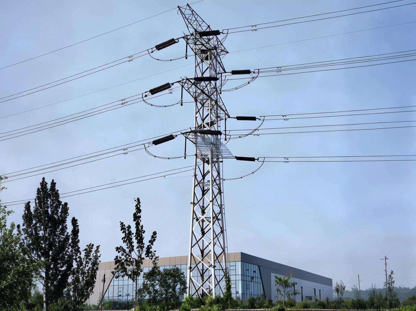
The structural integrity of high-voltage transmission infrastructure depends on far more than steel and concrete. At the foundation of every reliable power network lies a critical but often overlooked component: electric tower grounding systems. These systems serve as the primary defense against fault currents, lightning strikes, and dangerous voltage differentials that can threaten both equipment and human life. Without consistent, professional inspection protocols, even the most robustly engineered transmission infrastructure can become a serious liability.
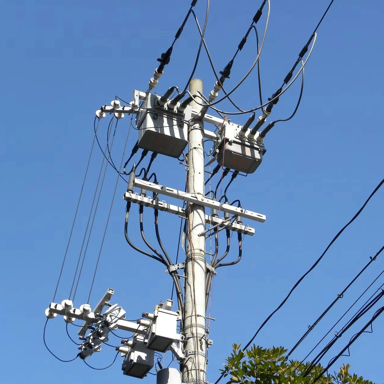
Regular inspections of electric tower grounding systems are not simply a regulatory formality. They represent a proactive engineering discipline that directly determines whether a transmission network can safely handle abnormal electrical events. As power grids expand and aging infrastructure faces increasing operational demands, the importance of systematic grounding inspections has never been more pronounced. Understanding why these inspections are essential requires a close look at what grounding systems actually do, how they degrade over time, and what the real-world consequences of neglect can be.
The Functional Role of Electric Tower Grounding Systems
How Grounding Protects Against Fault Currents
Electric tower grounding systems are engineered to provide a low-resistance path for fault currents to safely dissipate into the earth. When a phase conductor makes unintended contact with a tower structure due to insulator failure, wind damage, or equipment malfunction, the grounding system must immediately channel that energy away from the structure and any personnel in the vicinity. Without a properly functioning ground path, fault current can cause catastrophic arcing, structural damage, and lethal step-potential hazards around the tower base.
The effectiveness of this protection depends entirely on the continuity and conductivity of the grounding network. Ground rods, counterpoise wires, bonding conductors, and their connections must all maintain specified resistance values to perform their protective function. A single corroded connection or a fractured ground rod can compromise the entire system's ability to safely handle a fault event. This is precisely why periodic inspection is not optional — it is the only reliable way to confirm that the system will perform when it matters most.
In high-voltage environments such as 110kV transmission lines, the energy involved in a fault event is enormous. Electric tower grounding systems at these voltage levels must be capable of handling substantial fault currents for the duration required by protective relay systems. Any degradation in grounding performance directly translates into increased risk of equipment destruction and personnel injury during fault conditions.
Lightning Protection and Transient Voltage Management
Beyond fault current management, electric tower grounding systems play an equally critical role in lightning protection. Transmission towers are tall, exposed structures that attract lightning strikes with regularity, particularly in regions with high keraunic levels. When a lightning strike hits a tower or its overhead ground wire, the grounding system must rapidly dissipate the impulse energy into the earth to prevent flashover across insulators and damage to connected equipment.
The impulse impedance of electric tower grounding systems differs from their power-frequency resistance, and both parameters must be within acceptable limits for comprehensive protection. Soil conditions, moisture content, and seasonal temperature variations all influence how effectively a grounding electrode system can absorb and disperse lightning energy. Inspections that include ground resistance testing under varying seasonal conditions provide a much more complete picture of actual system performance than a single annual measurement.
Transient overvoltages caused by switching operations also place demands on electric tower grounding systems. As grid operators increasingly manage complex switching sequences to balance loads and reroute power, the grounding infrastructure must remain capable of handling these transient events without allowing dangerous voltage rises on tower metalwork. Regular inspection ensures that this capability is maintained throughout the operational life of the structure.
How Grounding Systems Degrade Over Time
Corrosion as the Primary Degradation Mechanism
The most pervasive threat to electric tower grounding systems is electrochemical corrosion. Ground rods and buried conductors are in continuous contact with soil, which contains moisture, oxygen, salts, and organic acids that aggressively attack metal surfaces. Galvanized steel components, while offering significant corrosion resistance, are not immune to degradation, particularly in acidic soils, coastal environments, or areas with high industrial pollution levels.
Corrosion reduces the cross-sectional area of grounding conductors, increases their resistance, and can eventually cause complete mechanical failure of buried connections. The insidious nature of this process is that it occurs entirely underground and is invisible during routine visual inspections of the tower above grade. Only systematic testing and periodic excavation of representative connections can reveal the true condition of buried electric tower grounding systems components.
Stray current corrosion presents an additional challenge in areas near electrified railways, cathodic protection systems, or other sources of DC current in the soil. These stray currents can dramatically accelerate the corrosion of grounding electrodes, causing deterioration at rates far exceeding what would be expected from natural soil chemistry alone. Identifying and mitigating stray current effects requires specialized testing that forms an important part of comprehensive grounding inspection programs.
Mechanical Damage and Connection Integrity
Physical damage to electric tower grounding systems can occur through a variety of mechanisms beyond corrosion. Ground disturbance from construction activities, agricultural operations, or erosion can displace or sever buried conductors. Frost heave in cold climates can mechanically stress connections between above-grade and below-grade components. Vandalism, though less common, represents a real threat in remote or unsecured locations.
Connection integrity is particularly critical because high-resistance connections can cause localized heating during fault events, potentially leading to connection failure at precisely the moment when the grounding system is most needed. Bolted connections between grounding conductors and tower steel must be inspected for corrosion, loosening due to thermal cycling, and mechanical damage. Exothermic welded connections, while generally more reliable, should also be visually inspected for signs of cracking or deterioration.
The grounding system of an electric tower is only as strong as its weakest connection. A comprehensive inspection program must therefore address not just the primary grounding electrodes but every connection point in the system, from the tower foot bond to the most remote counterpoise wire termination. This level of thoroughness is what distinguishes an effective inspection program from a superficial compliance exercise.
The Safety Consequences of Neglected Grounding Inspections
Personnel Safety Risks from Elevated Ground Potential
When electric tower grounding systems fail to perform adequately during a fault event, the consequences for personnel in the vicinity can be fatal. Step potential — the voltage difference between two points on the earth's surface separated by a human stride — can reach lethal levels around a tower with a high-impedance ground during a fault. Touch potential, the voltage between a grounded structure and the earth surface at a person's feet, presents an equally serious hazard.
Maintenance workers, inspection personnel, and members of the public who may be near transmission towers during a fault event are all at risk when grounding systems are not properly maintained. Utility companies have a duty of care that extends to ensuring that electric tower grounding systems are capable of limiting these hazard voltages to safe levels under all credible fault scenarios. Regular inspection and testing is the mechanism through which this duty is fulfilled and documented.
The consequences of a grounding failure that results in personnel injury extend well beyond the immediate human tragedy. Regulatory investigations, operational shutdowns, legal liability, and reputational damage can impose enormous costs on utility operators. Viewed from this perspective, the investment in regular inspection of electric tower grounding systems is not merely a safety expenditure — it is a fundamental risk management strategy.
Equipment and Grid Reliability Impacts
Inadequate grounding does not only create personnel hazards. It also threatens the reliability and longevity of the transmission infrastructure itself. When fault currents cannot be safely dissipated through properly functioning electric tower grounding systems, they may flow through unintended paths, causing damage to tower foundations, cross-arms, and connected equipment. Repeated exposure to poorly managed fault currents can accelerate structural fatigue and reduce the service life of expensive transmission assets.
Grid reliability is also directly affected by grounding system performance. A tower with degraded grounding is more susceptible to lightning-induced flashovers, which can cause line trips and supply interruptions. In interconnected grid environments, a single line trip can trigger cascading events that affect large numbers of customers. The economic cost of supply interruptions, combined with the cost of emergency repairs, far exceeds the cost of a systematic inspection program for electric tower grounding systems.
Modern grid operators are increasingly focused on asset health management and predictive maintenance strategies. Incorporating regular grounding system inspections into these frameworks allows utilities to identify deteriorating components before they fail, schedule maintenance during planned outage windows, and extend the operational life of their transmission infrastructure. This approach transforms grounding inspection from a reactive compliance activity into a proactive asset management tool.
Best Practices for Effective Grounding System Inspection Programs
Testing Methods and Measurement Standards
Effective inspection of electric tower grounding systems requires a combination of visual examination and quantitative electrical testing. Ground resistance measurement using the fall-of-potential method or clamp-on ground resistance testers provides the fundamental performance metric against which system condition is assessed. Results must be compared against design specifications and applicable standards to determine whether remedial action is required.
Soil resistivity measurement is an important complementary activity, particularly when ground resistance values have changed significantly since the previous inspection. Changes in soil resistivity due to drought, flooding, or changes in land use can affect grounding system performance independently of any physical deterioration in the grounding components themselves. Understanding the soil environment is essential for correctly interpreting ground resistance measurements and making informed maintenance decisions.
Advanced inspection techniques such as time-domain reflectometry can be used to identify discontinuities in buried grounding conductors without excavation. Thermal imaging during load conditions can reveal high-resistance connections that may not be apparent from resistance measurements alone. Incorporating these technologies into inspection programs for electric tower grounding systems enhances the ability to detect problems early and prioritize maintenance resources effectively.
Inspection Frequency and Documentation Requirements
The appropriate inspection frequency for electric tower grounding systems depends on several factors, including the voltage level of the line, the soil corrosivity, the local lightning exposure, and the age of the installation. High-voltage lines in corrosive soil environments or high-lightning-density areas warrant more frequent inspection than lower-voltage lines in benign environments. Most utility standards specify inspection intervals ranging from annual visual inspections to comprehensive electrical testing every three to five years.
Documentation is a critical component of any effective inspection program. Maintaining detailed records of ground resistance measurements, visual observations, and any remedial actions taken allows trends to be identified over time. A single measurement in isolation provides limited information, but a series of measurements taken over years can reveal gradual deterioration that would otherwise go unnoticed until a failure occurs. Good documentation also provides the evidence base needed to demonstrate regulatory compliance and due diligence.
Inspection programs for electric tower grounding systems should be formally documented in maintenance management systems, with clear assignment of responsibilities, defined acceptance criteria, and escalation procedures for out-of-tolerance findings. This organizational framework ensures that inspections are carried out consistently, that findings are acted upon promptly, and that the overall health of the grounding infrastructure is visible to asset managers and safety officers.
FAQ
How often should electric tower grounding systems be inspected?
The inspection frequency for electric tower grounding systems varies based on voltage level, environmental conditions, and applicable utility standards. As a general guideline, visual inspections should be conducted annually, while comprehensive electrical testing including ground resistance measurement is typically performed every three to five years. Towers in highly corrosive soils, coastal environments, or high-lightning-density areas may require more frequent testing to ensure continued safe performance.
What are the warning signs that a grounding system may be deteriorating?
Warning signs that electric tower grounding systems may be deteriorating include ground resistance measurements that have increased significantly compared to previous readings, visible corrosion on above-grade grounding conductors or connection hardware, evidence of soil disturbance near buried grounding components, and a history of lightning-induced flashovers on the line. Any of these indicators should trigger a more detailed investigation and, if necessary, remedial action before the next scheduled inspection cycle.
Can visual inspection alone confirm that a grounding system is safe?
Visual inspection alone is not sufficient to confirm the safety of electric tower grounding systems. Because the majority of grounding components are buried underground, visual examination can only assess the condition of above-grade connections and visible conductors. Electrical testing, including ground resistance measurement and, where appropriate, soil resistivity assessment, is essential to verify that the system will perform its protective function under fault and lightning conditions. Visual inspection and electrical testing are complementary activities, not alternatives.
What happens if a grounding system fails during a fault event?
If electric tower grounding systems fail during a fault event, the consequences can be severe. Fault current may flow through unintended paths, causing damage to tower structures, foundations, and connected equipment. Dangerous step and touch potentials can develop around the tower base, creating lethal hazards for anyone in the vicinity. Lightning-induced flashovers become more likely, increasing the risk of line trips and supply interruptions. In the most serious cases, grounding system failure during a major fault can contribute to cascading grid events with widespread consequences for power supply reliability.